Modern Sanayi Sitesi Başakşehir /İSTANBUL
info@demontelazer.com
+90 (212) 670 1 222
What is Laser Cutting
What is Laser Cutting
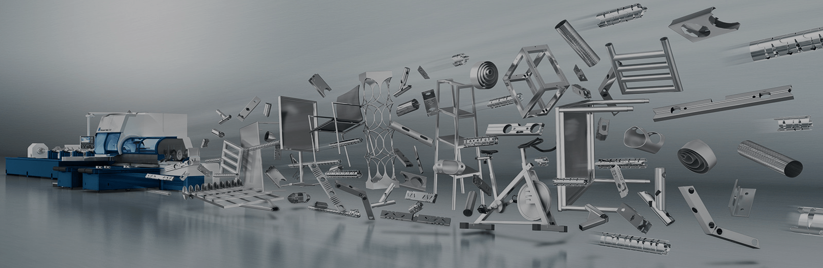
Trumpf 3050 – After the easier access to laser beam generation, the application areas of laser cutting have expanded. Its usage in engineering includes welding, cutting, and drilling operations. Laser-based manufacturing not only enables automation but also reduces production errors. By implementing lasers in various machines, production can be carried out 24 hours a day, leading to cost reduction through mass production. Laser cutting, in particular, allows for significant savings in molds and fixtures. Additionally, fewer machines are required, and human errors are minimized despite the high energy involved

In carbon dioxide laser machines, the laser is generated by applying electric current to carbon dioxide gas. Additionally, nitrogen and helium gases are added to the carbon dioxide laser, increasing its efficiency by around 30%. The laser mixture ratio is CO/N=0.81, while He is set to 1 (2.3). The laser beam travels a distance of nearly 10 meters inside glass tubes in the resonator section of the machine. As the gas passes through these tubes, the laser is generated by applying electric current between the two ends. Due to the laser being a beam of light, its direction can be changed using mirrors. Finally, the laser beam reaches the cutting head where the cutting process takes place. The gas cylinders used for laser generation should be located within a maximum distance of 10 meters from the machine. The application pressure is typically set between 6 and 10 bar

Many industrial lasers require the use of special gases for the generation of the laser beam. The quality and selection of the gas directly affect the reliability of the laser and the efficiency of the process. Laser gases are typically high-purity specialty gases. These gases are supplied to the machine either separately in individual cylinders or pre-mixed in predetermined ratios. The process parameters for pre-mixing or supplying gases in separate cylinders (gas flow rate, pressure purity, etc.) are determined by each laser machine manufacturer and provided to the machine under those conditions. The gases involved in carbon dioxide laser generation are Carbon Dioxide, Nitrogen, and Helium. Some gases may contain 4 or 5 components. (In addition to the atmosphere, CO, N, and Helium, CO, H, and Ne can be added) (4)

The layout of laser machines and proper loading is crucial for optimal performance. To achieve the highest efficiency, the sheet materials used in laser cutting should be of good quality. Rusty or uneven materials can degrade the cutting quality and may result in welding on the surface. The distance between the parts placed on the sheet should be at least equal to the thickness of the sheet. For circular cuts made by traversing the circumference, the minimum hole diameter should be 8mm. For direct drilling operations, the hole diameter should be half the thickness of the sheet. For thicker materials, only marking is performed instead of drilling holes

During the Computer-Aided Design (CAD) stage, the model of the workpiece to be manufactured can be designed, and manufacturing drawings can be created. Creating manufacturing drawings using AutoCAD software provides great convenience. Drawings can also be made using programs specific to laser machines. If the drawing is created using AutoCAD, it is saved as a .dwg file format, and the drawing should not have multiple layers. Then, this drawing is saved as a .dxf file format in AutoCAD software. The program specific to the machine converts the drawing into a .geo file format using subprograms, which will be used in the machine’s program. If the drawing is done in the program specific to the machine, it can be directly saved as a .geo file without the need for conversion

After these steps, the program of the machine is executed, and a layout plan is prepared on the sheet metal for the part or parts to be cut. On a plate with known dimensions, a certain number of identical thickness parts or multiple different parts can be placed as long as the thicknesses are equal. This is a suitable method for cutting parts in batches. The previously prepared .geo file or files are called, and they are placed on the sheet metal in the desired quantity and variety. Then, the cutting rules are determined. In the Computer-Aided Manufacturing (CAM) section, the cutting simulation of one or more workpieces is performed using the program. Various errors that may occur during cutting are evaluated. For example, if the hole diameters are too small, laser beam entry is performed from different locations, or if the parts are placed too close, the distance between them is adjusted. The movements of the laser head are displayed on the screen, and changes can be made if desired. Local deformations on the part are taken into account when adjusting the head movements. The laser table is determined, and a number is assigned to the program. After the placement process on the sheet is completed, a .taf file extension, which is the file format to be sent to the machine, is created. Then, this file is transferred to be called during the cutting process from the computer when it is time for cutting. When the operator is ready to perform the cutting, the part is called from the computer using the given program number

The operator application page (Operator Setup Sheet) and the movement pattern of the laser cutting head are taken on paper and given to the operator for the operator to perform operations and intervene in case of any issues. The page prepared for the operator generally includes the program number, date, material type, weight and dimensions of the material, number of plates to be cut, total cutting time, cutting length, file names of the parts to be cut with the .geo extension, and page name. In addition, information such as the program number, cutting time of that part, cutting length of that part, weight, and the number of points to be processed inside the part can be seen.
After the sheet metal is inputted, the parts are placed and the thickness is determined, the weight of the sheet metal plate and the size of the lens are determined. The cutting time of the laser machine operation can also be seen instantly. If a large number of cuts need to be made from a program in the machine, it can be called repeatedly and performed. The sheet metal plate can be placed on the machine with the help of hand, forklift, or vacuum arms. There are two cars on the machine. The sheet metal material to be processed on one of these cars is placed on the other car while the processing is in progress. When the car that finished the process is taken out, the other car that will enter the process is taken in. This way, a significant amount of time is saved. As a result, while the cut parts are being collected, the sheet metal processing starts on the other car.
Once the machine is running, the glass partitions must not be opened under any circumstances. These glass partitions are made of materials that protect against radiation and the effects of laser beams on the eyes and skin. The air requirement of the machine is provided by a compressor. Additionally, the environment where the machine is located must be clean. The computer on the laser machine is used to call programs, perform operations, and view current operations. Two different types of programs can be created for parts drawn with technical drawings. The first one is the program consisting of the part. This program is generally preferred for parts with smooth shapes and a large quantity of production. Only these parts are placed on the entire sheet metal plate. Problems can be identified by simulating the program. The movements of the laser head on the sheet metal plate can be modified. Entry points of the laser on the sheet metal plate, paths followed by the laser during cutting, and the idle movements of the laser head can be observed. They are all seen in different colors. Dotted areas represent the initial entry points of the laser, rectangular areas represent the areas where laser cutting is performed, and zigzag lines represent the idle movements of the laser head. In this way, it is possible to see where the laser will be restarted in case of any issues with the output. This simulation is also available on the computer screen on the machine.
Once the part seen above is drawn using the AutoCAD program and the described procedures are followed, the movements of the laser head are performed with the program that is seen. Then, the cutting process can be carried out on the laser machine. Secondly, a program is created by placing multiple different parts or pieces on the sheet metal plate. With this program, programs that minimize waste can be created by placing smaller-sized parts between or on the edges of asymmetric parts. As seen in Figure 3, 15 different parts are placed on a sheet metal plate. In this cutting, the waste that would occur due to the shapes of the materials is reduced by placing small parts on them. With this programming, all the parts to be sent will be together, ensuring control over the material.
In recent years, laser cutting machines imported as technological manufacturing machines have provided great convenience for production in the automotive sector in our country. Various factories operating as automotive sub-industry have outperformed their competitors by using laser cutting machines. The general features of the laser machine, the advantages provided by using the laser machine, the materials and thicknesses for which the laser machine is used for cutting, what to pay attention to during part programming, and the programming stages of a manufacturing process are mentioned in the study. When programming on the laser machine, attention should be paid to certain factors, and explanations are provided for the more effective implementation and understanding of the programming stage.
One of the drawbacks observed in the manufacturing process on the laser cutting machine is the hardening of the material in areas where hole drilling is done in a single stroke. If operations such as threading are planned for these areas instead of drilling in a single stroke, the program should be reviewed to only perform marking on the areas to be drilled. To use the laser machine, it is necessary to understand the structure and features of the machine well. The processes from placing the cutting material on the machine to taking out the cut parts must be closely monitored. To be able to program, a good understanding of the machine-specific program is required. Additionally, programming can be done much more easily with AutoCAD knowledge. Sheets, hot-rolled sheets, galvanized sheets, stainless steel, aluminum, copper, brass, titanium, plexiglass, and texts and patterns are cut with a precision rate of 3%.